 button from the
 During solution the model is loaded with a combination of factored Load Categories. These combinations, load factors, and other parameters are defined on the Load Combinations Spreadsheet. Most standard load combinations are included in the program. See Solution to learn how to solve load combinations.
To Add Load Combinations Manually
To Add Auto-Generated Building Code Combinations
button from the Note
 button on the Window Toolbar.
 button
 The Load Combinations Spreadsheet records the combinations of
loads for solution and may be accessed by selecting Load Combinations
on the
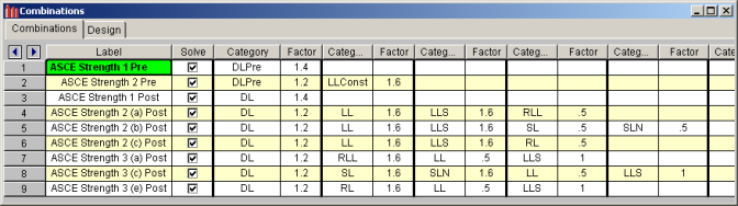
The first field, the Label, is strictly for the user's reference. Enter any descriptive label you wish and it may be displayed with the results when the combination is solved.
The Solve
box is used to indicate which combinations should be included
The next eight pairs of fields (Category, Factor) are for defining what load categories are to be part of the combination, along with factors for each. Select load categories from the drop down lists in the Category columns of the spreadsheet. See Load Categories for a list of the categories available for use.
Enter in the Factor field a multiplier to be applied to the load category being included. If you are designing an unshored composite beam system, you should define at least one pre-composite load combination. If you fail to do so, the beams will not be designed to resist the effects of the pre-composite loads.
Note
The first field, the Label, is strictly for the user's reference. Enter any descriptive label you wish and it may be displayed with the results when the combination is solved.
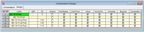
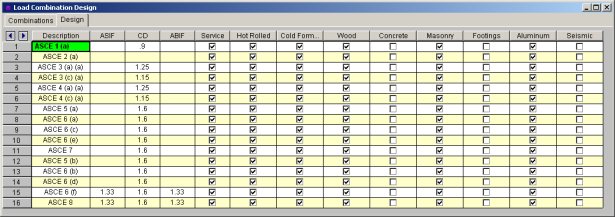
The ASIF column is used to set the allowable stress increase factor used for both the AISC: ASD code checking and ACI 530 ASD (masonry allowable stress design). See Allowable Stress Increase regarding its usage for Hot Rolled Steel.
The CD factor is the load duration factor and is only necessary for NDS timber design using ASD (see Load Duration Factor). Note: this is KD for Canadian (CSA O86) wood design.
The lambda factor is the time effect factor and is only necessary for NDS timber design using LRFD (see Time Effect Factor).
The Service check box only applies to RISAFloor ES concrete slab floors. Load Combinations with the Service check box turned on will be checked for the Slab Point Deflection results and will also have the plate stiffness factored. See the Elevated Slabs - Analysis topic for more information.
The last check box for Connection defines
Note
Entering a value/factor in the field labeled ASIF (Allowable Stress Increase Factor) indicates that the load combination should be treated as a wind/seismic load combination.
If AISC 9th Edition ASD code checking is selected, the allowable stress increase factor entered in this field is applied to this load combination.
For Wood design, the load duration factor (CD) is entered in the CD field on the row that the particular CD factor applies to. Different load combinations would have different CD factors. For example, per the NDS code, a load combination that had only dead load, would have a CD factor of "0.9", while another combination that was comprised of dead load plus wind load would have a CD factor of "1.6".
The CD factor will only be applied to wood code checks on wood members. "Wood" members are those members whose material properties are defined on the Wood tab of the Material Properties Spreadsheet.
Note
Major portions of the load combinations
that are specified by building codes are included and may be applied to
the model for solution. These combinations may be inserted
by selecting the button from the
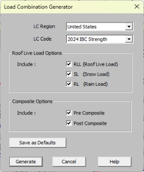
The LC Region refers to the various regions supported by the program (U.S., Canada, India, British, et cetera).
The LC Code refers to the actual code used to build the load combinations. For the United States, there are a number of different codes that could be used to build load combinations. If the only option is Sample, that means that no load combinations have been input for that region. See Customizing the Load Combination Generator for more information on how to add or edit combinations for that region.
The Roof Live Load Options allow the user to specify how complex the load combinations including roof live loads should be.
Placing a check in the box next to RLL (Roof Live Load), SL (Snow Load), and/or RL (Rain Load) will indicate that the selected load categories are to be included in the generated load combinations. If the box next to SL (Snow Load) is checked, the load combinations will include the Non-Shedding Snow Load category, SLN, as well as the SL load category.
The Composite Options allow the user to specify whether Pre-Composite and/or Post-Composite loads are to be included in the generated load combinations.
If the Pre-Composite checkbox is checked, load combinations containing the DLPre and LLConst load categories will be generated based on the selected code.
If the Post-Composite checkbox is checked, 'traditional' load combinations containing the DL, LL, LLS, and any of the categories included in the 'Roof Live Load Options' section above will be generated based on the selected code.
For more information on any of the load categories mentioned in this section, see Loads - Vertical Loads.
The Save as Defaults button may be used to establish the current load combination generator settings as the defaults for future use. Clicking the Generate button will generate load combinations in the Load Combinations Spreadsheet based on the selected options.
The following loads are not generally included in the standard combinations but may be added by editing the combinations in the spreadsheet or by modifying the source document itself. For more information, see Customizing the Load Combination Generator below:
| Category Code | Description |
|---|---|
|
TL |
Long Term Load |
|
HL |
Hydrostatic Load |
|
FL |
Fluid Pressure Load |
|
PL |
Ponding Load Category |
|
EPL |
Earth Pressure Load |
|
DLConst |
Construction Dead Load |
|
OL# |
Other Load Categories |
Note
The Load Combinations for each region are contained in an XML file which can be opened and edited using a standard spreadsheet program. An example of on of these XML files is shown below:
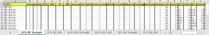
The name of the file itself becomes the name of the Load Combination Region that appears in the Load Combination Generator. Each XML file has a series of "worksheets" and the name of each worksheet will be the name of the Load Combination Code that appears in the Load Combination Generator. The user may add, edit or modify these documents to completely customize the available load combinations.
Note
The first row of each sheet is reserved
for the column headers. The recognized column headers are as follows:
Label,
Solve,
Other than Label and the Category / Factor pairs, the user may omit columns. If a column is omitted, the default values will be used for those entries. The order of the column labels is optional except for pairs of Category and Factor. For the program to correspond the Factor with correct Category, the user should always provide Category label PRIOR to the corresponding Factor. The user may insert blank columns or columns with other labels than described above. In those cases, the program omits those undefined columns.
Note